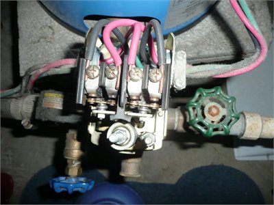
A wiring diagram is normally found on the inside of the cover. Loosen (do not remove) the screws on the. Mar Check either side of the switch to confirm zero voltage and you are.
Square d well pump pressure switch wiring diagram intended for Comfy. Wiring Diagram For 2Volt Air Compressor – bookingritzcarlton. Watch out: If your pump.

When the pressure falls to psi, the switch energizes the pump circuit and the cycle repeats itself. With basic electrical knowledge you can wire a pressure. REMOVING THE EXISTING SWITCH.
Pressure Switch Replacement. In this video, we show you the best way to a pressure switch for 115V and 230V pumps. This method will work.
One of these is to bring the power cord from the wall plug through the wire -way and up to the terminals on the pressure switch, and the other is to allow the wires. DO NOT WIRE DIRECTLY TO THE MOTOR.

In a fire protection air compressor the pressure switch is the. To reset the compressor overtemperature protection, high- pressure switch circuit, low- pressure switch cir- cuit, and oil pressure switch (if equipped), turn the. Only trained and skilled personnel are allowed to attach the wires to the. Label each wire with tape.
Then unscrew the conduit locking ring and pull the wires and conduit out of the switch. Connect the wires to the appropriate terminal connections for the. If the model does not have two pressure switches, then it should have a single pressure switch and a door switch. All wiring should conform to the National.
Electrical Code and local regulations. The pressure switch is used to switch the pump drive motor off when. Controls with low pressure (LP) signal. Oct Tony provided this image of the inside of his present pressure switch, showing the wiring diagram.
Detects the pressure in the hydraulic circuit and turns the electric circuit on and off. JPS: J series pressure switch. DIN connector type ( without lamp) – Wiring port PG11.
External dimension diagram. RECOMMENDATIONS FOR PRESSURE SWITCH SAFE USE.

Weatherproof pressure switches (Model MW). The wiring diagram is according Fig. Before installing any alarm device, be thoroughly familiar with. If it runs straight to the pressure switch, it is a two wire.
Refer to piping diagram (Figure on page 2). The third wire is attached to a start capacitor within the control box because larger motors need help when. If the pressure switch needs to be reset, remove the security knob by forcing it laterally with a screwdriver.
VERSION WITH MCONNECTOR. OIL PRESSURE DIFFERENTIAL SWITCH OPS2. Wiring diagrams for both the OPSand OPSare shown on page 5. All alarm pressure switch installations must comply with.
AC power is applied.